💻 Atari 260ST RGBtoHDMI Installation
Martin Döring, last modified, July 4, 2022Three of four modifications to bring my Atari 260ST back up to date I have now installed: The main memory was extended by 8 MB AltRAM with the Cloudy-Storm ST and four times 256 KB TOS are now flashable and selectable for booting, a MouSTer was installed to be able to connect modern wireless mice.
This last article finally describes the installation of a RGBtoHDMI extension to be able to use the Atari with any modern TFT screen.
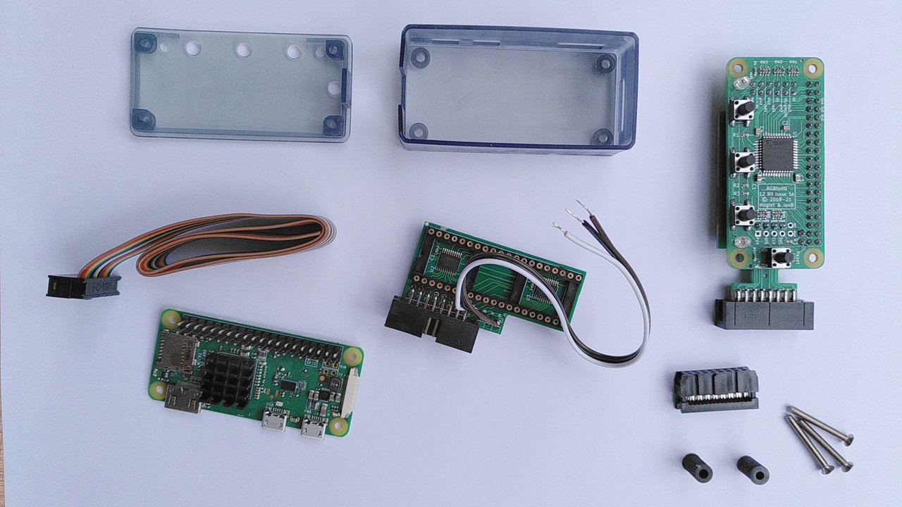
I ordered the RGBtoHDMI board and the corresponding shifter adapter on the internet. This is open hardware that anyone can freely rebuild. I can solder well, but I don't dare to use SMD technology, so this time I bought it ready-made.
Hardware installation
The hardware setup is actually quite simple: The RGBtoHDMI board is plugged onto a Raspberry Zero or Zero W. The newer Zero 2 is not suitable. It has a more powerful processor, but the control of the GPIO pins is about 30% slower. But that's exactly what we need for this video capture device - and extremely fast.
It's also important to note that the Pi Zero must not have a heatsink glued to the processor, as that will get in the way.
Once both boards are connected to the GPIO header, the whole thing is installed in the case that came with me. I don't know if this is good in the end, because the waste heat can escape even worse. But apparently that is ok. The Pi can be operated at temperatures up to 70 degrees without damage.
Next we install the shifter adapter board into the Atari ST. The video shifter itself is hopefully socketed. My procedure for removing chips is always to first take a smaller flat screwdriver and lightly pry on the chip with it. Then I take a really big screwdriver that is almost as wide as the chip and turn it axially so that the pins of the chip are levered out of the socket sensitively with left and right rotation respectively. By turning the fat screwdriver like this, I can lever the pins out of the socket in a very controlled manner without anything slipping off.
Before we can install the adapter for the shifter, the metal cage must either be completely removed, i.e. desoldered, or at the rear end, where the ribbon cable comes out, a sufficiently large opening must be created with tin snips. Simply omit the cover or modify it accordingly.
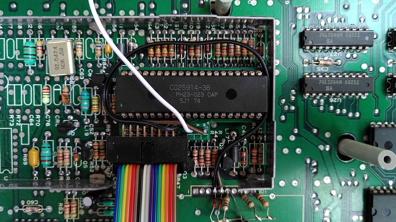
Once the shifter is out and the sheet metal removed, we can put the adapter on the socket. There are two things to note here: On the 260ST, there is a small transistor in the way where the board's connector header is. It has to be carefully bent away a bit so that the ribbon cable can be plugged in later.
Now we can plug in the adapter. Make sure that the adapter slides into the socket with the pins on the left and right side at the same time. Afterwards the shifter has to be put back on top. Again, be careful not to bend any pins.
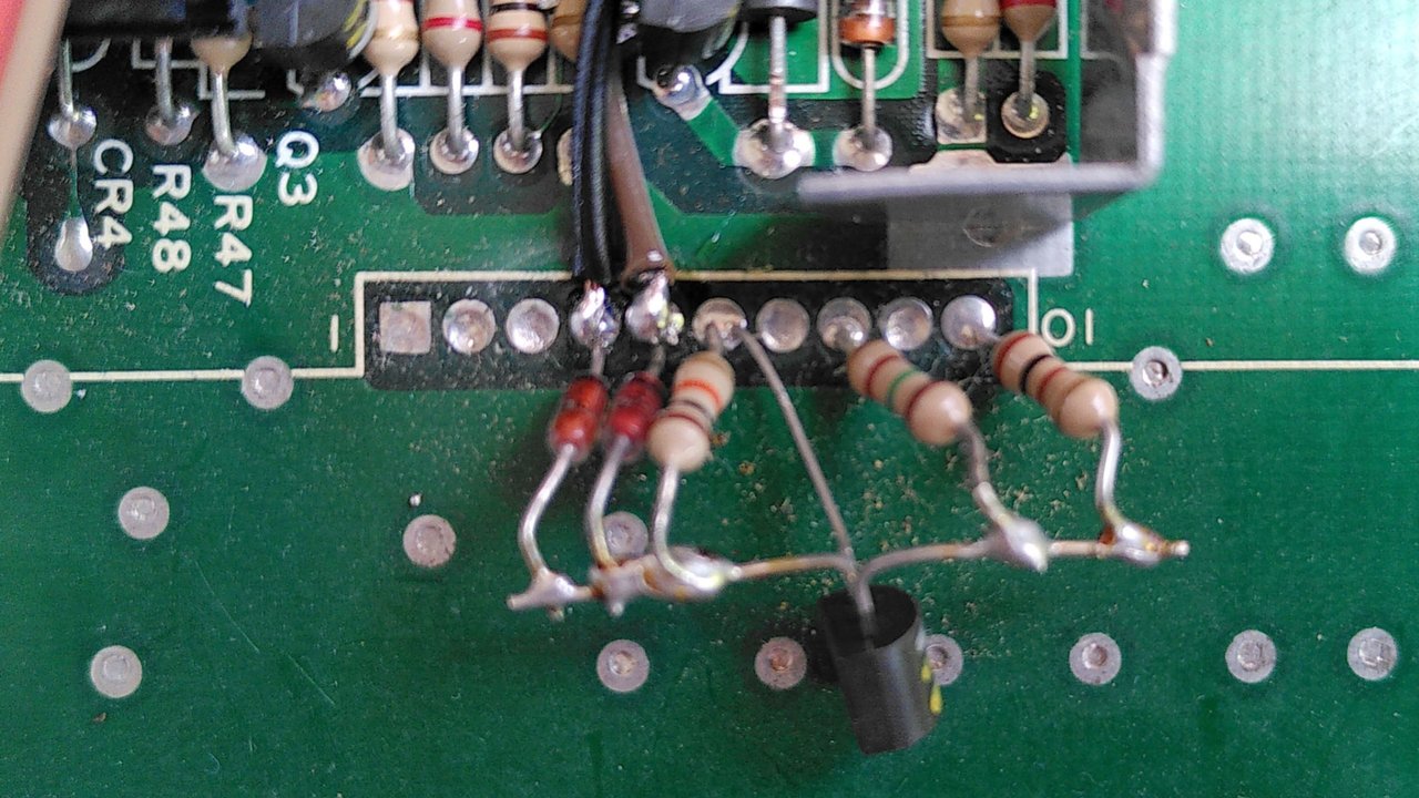
From the shifter adapter three cables are led out, in my pictures with the following colors: These are HSync (black), VSync (brown) and Blank (white). The first two must be soldered to the modulator connector, as shown below, regardless of whether a modulator is actually installed or not. In the picture the modulator connections are numbered from left to right.
- VSync, black cable, to pin 4 of the modulator
- HSync, brown cable to pin 5 of the modulator
- Blank, white, to some diode near the shifter, but I haven't been able to locate it yet. It works fine for me without it, funnily enough. Less is more. :-)
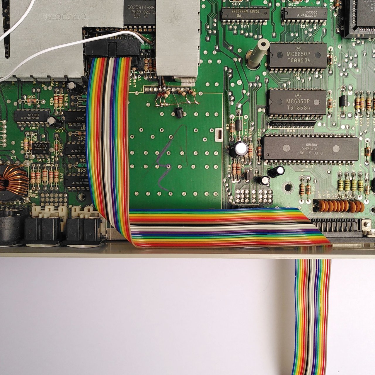
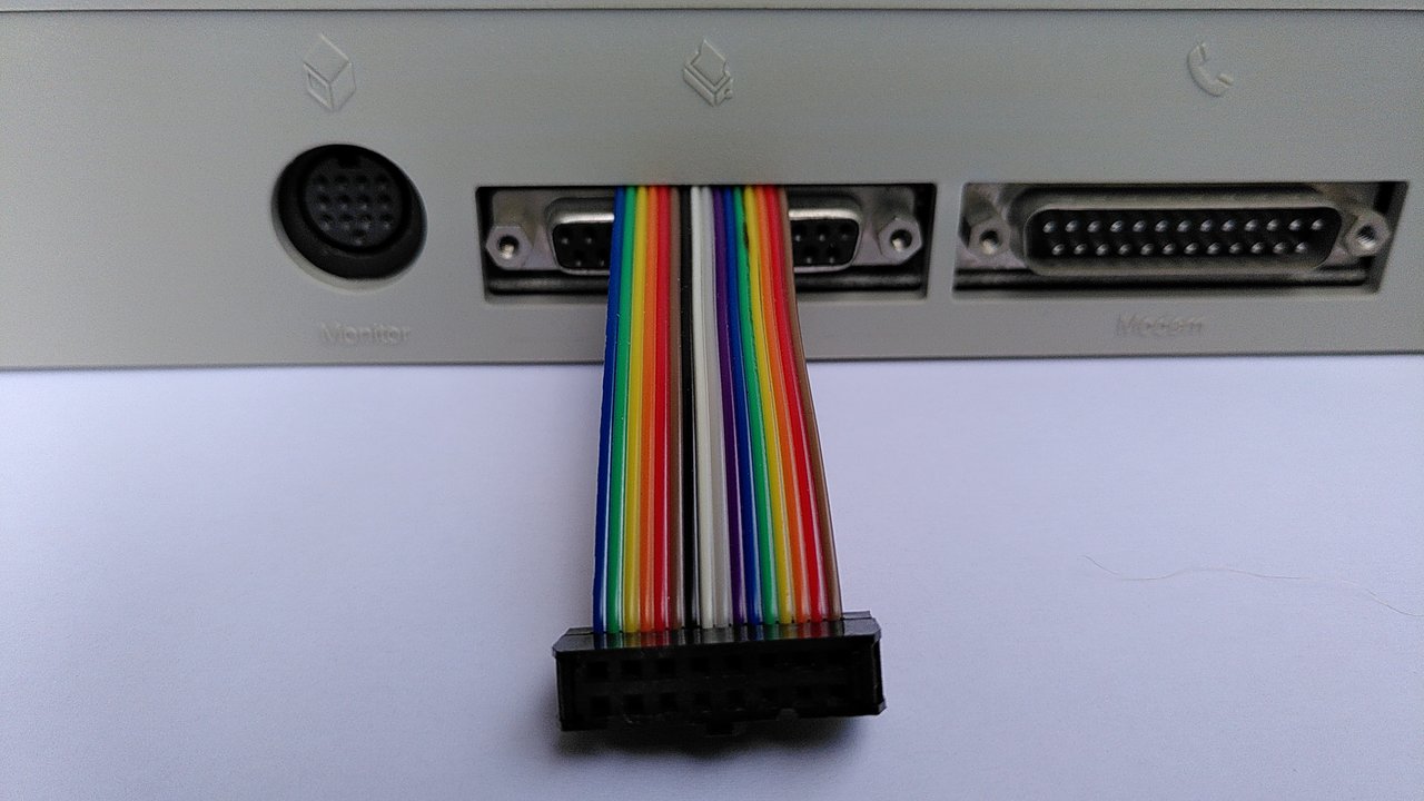
At the ribbon cable one side is still without connector, here the provided connector must be pressed on. Caution: This must be done so that the cable goes basically flat from the shifter adapter into the RGBtoHDMI without twisting. The plug must be pressed on in such a way that the bulge on the shifter adapter is at the top and on the side of the RGBtoHDMI at the bottom!
The pressing on itself can not be easily undone, so make sure that everything is the right way around. For pressing on, I put the connector between two wooden slats and pressed neatly.
I did it in such a way that I pulled the cable through the printer port before pressing it on. If you want to do this later, you only have to take the board out of the case. Here is a picture of how the cable is routed so that the case screws are not in the way later:
Software
Now we need a MicroSD card for our Raspberry Pi Zero. Mine has 32 GB, it must be formatted with Fat32, which most cards up to 32 GB already are. After that, we need to dump the firmware from the ZIP archive directly into the root directory. You can get it here:
Download below the long "Detailed list of changes".In my case the file was called RGBtoHDMI_20211224_c97f06a.zip. Once the MicroSD card is prepared like this, we plug it into the Pi. The now ready to use RGBtoHDMI is now connected to the shifter adapter with the flat bank cable. The device is powered by the Atari when it is switched on, no external power supply is needed.
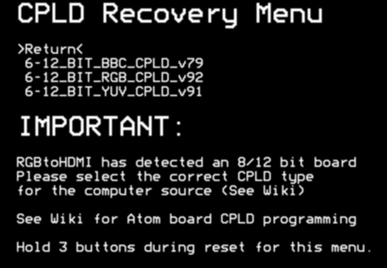
Attention. The RGBtoHDMI is set up at first startup so that the correct CPLD program is not yet selected. This is the logic programming to be loaded into the CPLD chip, similar to an FPGA, configurable hardware.
The device has a simple operation, there are three buttons next to each other:
- Button 1: Menu (in, out, select).
- Button 2: Down
- Button 3: Up
Simple, isn't it? We ignore the fourth button (reset) here. Now we go with the second button so far down that we land in the "CPLD Recovery Menu" and select there with up/down the second entry "6-12_BIT_RGB_CPLD_v92":
Programming with the menu button takes a few seconds. Afterwards the Pi reboots. If it has rebooted, we now move down with the middle button until we are at "Profile", go in there with Menu (first button) and select with up/down then "Atari ST", not "Atari STe".
Once we have selected that, you should already see a picture of our little green desktop. Now we go to the menu and save the configuration.
The RGBtoHDMI now recognizes our resolution automatically. Because the colorful 50 Hz resolution and the monochrome 71 Hz resolution both have a so-called sub-profile, which is taken automatically suitable in each case.
Now we ask ourselves, how do we get to a monochrome resolution? Either we plug a monochrome screen connector cable into the normal old 13-pin screen connector or we buy such a 13-pin DIN connector and solder ourselves a connection of pin 4 and pin 13. When plugging in, the Atari then boots in ST-High mode next time. That's just the way it is with the ST.
Conclusion
Using the Raspberry Pi as a video capture device is great. The advantage of this solution compared to all solutions, which are simply connected to the video output, is, that here we take the video signals unaltered digitally at the shifter with the shifter adapter. So the CPLD chip controlled by the Pi gets a completely unaltered and sharp video signal. The image quality is absolutely captivatingly sharp.
Unfortunately, it is not possible to use higher graphic resolutions. The reason is that the video shifter of the Atari is a pretty fixed thing, you can't adjust much except for the selection of the three resolutions. This solution is not a graphics card, but only a video capture - which by the way also allows screenshots of the desktop (or game) with a short press of the middle button. Here is an example in the middle resolution:
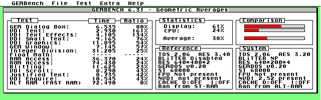
If you like, you can play around with the other settings. You can select the pixel ratio between Atari pixels and the display monitor, you can fix the monitor resolution if you don't like the default resolution and much more. There is a lot of room for trial and error here.
My Atari 260ST is now ready for the next 37 years of operation ;-)
Links
The RGBtoHDMI WikiEternally long thread in the Atari forum
Another article by Łukasz Jokiel on the same topic
Other ways to connect the Atari ST (Youtube)
Back
Privacy Information